PDP11 Hack plus V2
It’s been a while, life has been difficult of late for a number of reasons which I won’t go into. However I’m slowly getting my electronics Mojo back, so I’ve been working on the PDP11-Hack board
With the previous version I think I tried to put too much in too quickly, so I’ve gone back to basics. The new board (V2) has replaced the discrete glue logic with a PLD and I’ve removed the 16bit RAM and address decoding, again, trying to keep it simple and make sure everything works. A PDF can be found here. The PLD code was written by my partner as she’s done a number of these and is used to the very 90s GUI for programming them.
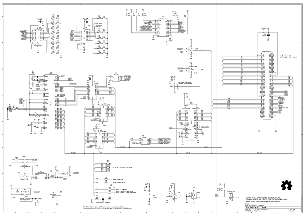
As you can see the use of a PLD and removal of RAM has made life a lot simpler, I’ve also added a couple of extra bits, firstly LED drivers for key signals, These may help with debugging, plus who doesn’t like blinken lights on their computer?
Most notable is the 96 way connector on the right hand side of the schematic, this brings out all the key signals so I can attach this to a back plane and then make add on boards, like RAM, Display, and who knows what else. So this is going to be put on a Euro-card 160mm x 100mm. I have bought a 4 slot (and 8 slot) Euro-card backplane from this guy on eBay for this, that should give me a number of options for expansion. I’m also thinking that for future processor things a flexible backplane could be useful.
I’ve also added some pull up/down resistors for the power up configuration, this should ensure it boots to ODT on power up and doesn’t expect a floating point unit and a few other bits.
PCB routing is nearly done, and I’ll share a render when it’s done, and pictures when the board arrives.
Once the board is proven, I do intend to make the schematics and gerbers publicly available.