PDP/11 Hack+
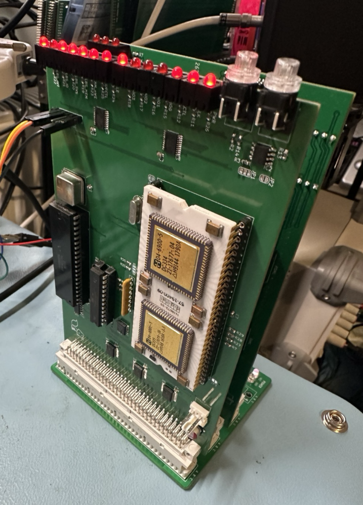
I’m really pleased to say that over the holiday I managed to get some time and built up my RAM/ROM/Text Display PCB for my DCJ11 system.

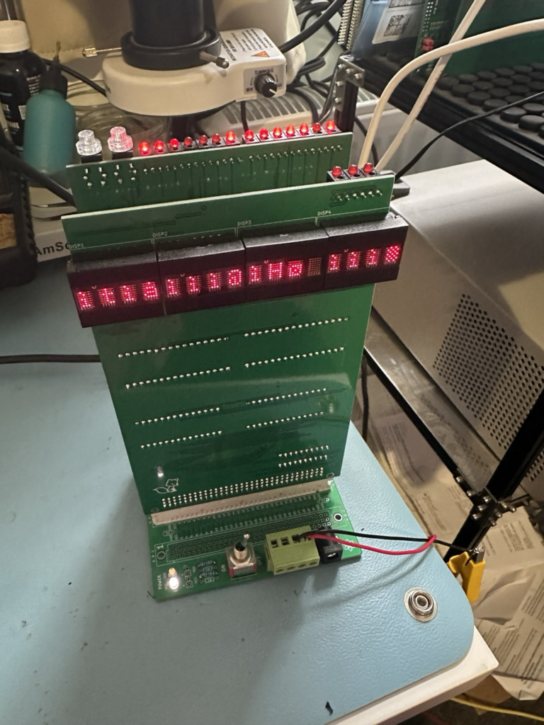
First power up (just RAM) worked, I could write and read from the memory, YAY! Next up I added the display and that also worked (you can see the block on the right hand most character), however I couldn’t then write to the UART memory address, after a bit of digging I’d got my PAL code wrong for the memory address decoding. I forgot that the DCJ11, despite being a 16 bit chip, can only access 16bits of address.

A quick bit of rework of the PAL and I got that working too!
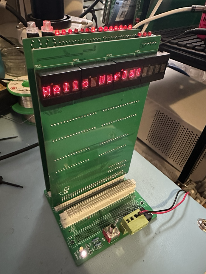
So the first test had to be “Hello World!”, initially I did this by writing a value to a memory address;

Next I added the ROMs and sure enough I could now read a value of “377” (0xFF in hex) in the places where the ROM was, and writing a value then reading it back showed it hadn’t changed, yay.
The reason the display is on the back is that I want to be able to have the DCJ11 chip facing out as well as the displays, so you can just rotate the back plane to see all the cool stuff (yes I know, it’s daft, but..)
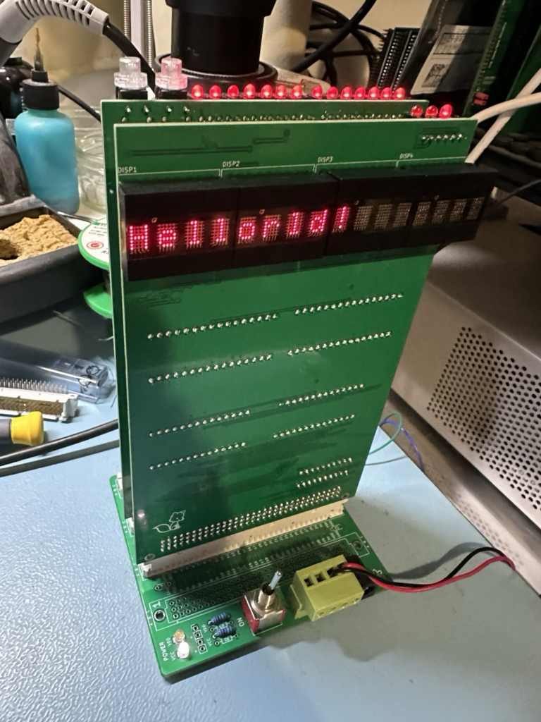
So what next? Well if you follow Usagi Electric on YouTube you’ll know he made a typo whilst entering his “Hello World!” text on his Centurion mini computer resulting in “Hellorld!” being displayed, so I had to do the same of course.

So what’s next for the project?
- I’d like to add a dot matrix style display and see if I can get Game of Life running on it, and ideally from ROM, so I need to make a board for that.
- I would also like to add a reset signal to the display so it starts clear rather than being full of junk. This was a mistake on my part as brought the active HIGH reset from the DCJ11 board onto the back plane and the displays need an active low, simple enough to fix with a bodge wire.
- What I’ll then do is create a github account and repository for the schematics, PAL code and any test code I make.